.
Abstract
Assimilation is basically an increase in the similarity of one perception to a second perception. Assimilation and disparity produced visual lines help to explain effects of disparity including accurate perceived depth and the perceived horizontal coordinates of diplopic percepts that other analyses of disparity do not explain. The present explanation’s gist follows. A fixated far object and a non-fixated disparity producing near object are in the median plane. Each eye results in a neural representation of the near object that is called a disparity representation. Each depicted disparity representation is on a depicted disparity produced visual line. Each point of this visual line has both a specific three-dimensional distance (3D) and specific horizontal coordinate. Each disparity representation’s 3D completely assimilates (becomes the same as) the fixated object’s perceived 3D. This assimilation-produced specific 3D and each disparity produced visual line prescribe that each disparity representation’s horizontal coordinate is to the left or right, consistent with figures in the literature. These left and right horizontal coordinates assimilate (they become more similar to each other) and hence become more median. Each more median assimilation-produced specific horizontal coordinate and each disparity produced visual line prescribe that each disparity representation’s 3D is nearer. The nervous system’s visual line functions analogously. Hence the non-fixated object is perceived as nearer.
.
The present paper explains why disparity results in accurate perceived depth. It also explains, for disparity produced retinal images that are equally to the left and right of the fovea, why more disparity results in perceived horizontal coordinates that are more midline including that a midline coordinate is perceived. These results will be basically explained by the occurrence of assimilation between three-dimensional distances (3Ds), the occurrence of assimilation between horizontal coordinates, and each eye’s visual line. Previous analyses do not explain the accurate depth result and they at best partially explain the more midline horizontal coordinate results.
A disparity representation will be referred to. Disparity results in two neural representations, each eye eventuating in one of them, and each of them will be referred to as a disparity representation.
A neural representation for a simple object, including a disparity representation, is conceived of as including neural representations of at least a 3D, horizontal coordinate, and set of features. Also, these representations may or may not enable a consciously perceived 3D, horizontal coordinate, and set of features. Enables means to make possible.
Large, moderate, small, and minimal disparity results will be covered in this order in separate sections.
The current Introduction and the majority of this paper’s sections include subsections. The Introduction, sections, and subsections will occasionally be referred to.
Assimilation
Assimilation is basically an increase in the similarity of one perception to a second perception. Assimilation presumably occurs when the neural representation underlying a perception becomes more similar to the neural representation underlying a second perception.
An illustration of evidence of assimilation between 3Ds is that the perceived 3D of a monocularly viewed rectangle became about the same as the 3D of a binocularly perceived square (Gogel, 1956). An illustration of a result that is evidence of assimilation between horizontal coordinates is that the perceived horizontal coordinate of a vertical line became similar to the horizontal coordinate of an adjacent rectangle (Ganz, 1964). Assimilation of a color toward another color is a more familiar type of assimilation.
An assimilation produced increase in similarity that is consciously perceived does not necessarily occur. Accordingly, presumably a neural representation that becomes more similar to another neural representation may or may not enable a conscious increase in this similarity.
Results that are evidence of assimilation between coordinates, 3Ds, and features are often referred to in the literature in different ways. “Capture” refers to a perception that becomes the same as a second perception (e.g. Ramachandran & Cavanagh, 1985). “Attraction” refers to a perceived coordinate that becomes similar to a second perceived coordinate (e.g. Smith, 1954). The “equidistance tendency” refers to a perceived 3D that becomes similar to another perceived 3D (e.g. Gogel, 1965). “Interpolation” refers to a perceived 3D that becomes similar to a disparity produced perceived 3D (e.g. Howard & Rogers, 1912).
Visual Line Explanations
A disparity representation is thought of as being on its eye’s depicted visual line. This line starts at a point on an eye’s retina, proceeds through the eye’s nodal point, and terminates at a 3D. Each point of this visual line has a specific 3D and specific horizontal coordinate. Visual lines are depicted, for example, in each of Figures 2A-2D.
Visual line explanations of disparity’s effect on elemental perceptions will be based on one or the other of two premises. One premise is that an eye’s visual line and a disparity representation’s specific 3D usually prescribe (indicate, accurately predict) the disparity representation’s specific horizontal coordinate. A second premise is that an eye’s visual line and a disparity representation’s specific horizontal coordinate usually prescribe the disparity representation’s specific 3D. Likewise, these premises are that a visual line and a specific 3D prescribe a specific horizontal coordinate and a visual line and a specific horizontal coordinate prescribe a specific 3D.
The nervous system’s visual line is held to function analogously. Bases for the nervous system’s visual line should include neural information of the positions of the eyes’ retinal images and neural information of the eyes’ rotations.
Visual line premises are supported because explanations that rely on them work. For example, the preceding paragraph’s first visual line premise helps to explain the specific horizontal coordinates of diplopic percepts. These explanations are in the “Visual Line Explanations of the Specific Horizontal Coordinates of Diplopic Percepts” section of the immediately following division.
A Horizontal Coordinate Instead of a Horizontal Direction
A horizontal coordinate is denoted, for example, by a specific left or right horizontal distance from the median plane. Four reasons a horizontal coordinate instead of a horizontal direction will be considered follow. First, recollecting, visual line explanations maintain that a specific horizontal coordinate is prescribed by a visual line and a specific 3D and that a specific 3D is prescribed by a visual line and specific horizontal coordinate. Second, assimilation should be between horizontal coordinates, because the horizontal angular directions to two far points results in a large horizontal distance between them, the same horizontal angular directions to two near points results in a small horizontal distance between them, and because the horizontal distance between points affects the amount of assimilation that occurs (Born, Kruger, Zimmermann, & Cavanagh, 2016; Ganz, 1964; Rentschler, Hilz, & Grimm, 1975). Third, the perception of a horizontal coordinate instead of an angular direction tends to be measured (e.g. Born et al., 2016; Ganz, 1964; Prinzmetal, 2005; Rentschler et al., 1975; Werner, 1937). Fourth, this paper’s explanations of effects of disparity do not call for considering the effect of the egocenter on perceived direction.
Assimilation between 3Ds and Visual Line Explanations of Why
a Large Disparity Results in Zero Perceived Depth
and Specific Left and Right Horizontal Coordinates
The present division provides evidence that a large disparity results in zero perceived depth between the perceived 3D of the diplopic percepts that it results in and the 3D that occurs with fixation. The present division then puts forth an assimilation between 3Ds explanation of this zero perceived depth. It then supports this explanation. It then indicates that for disparity produced retinal images that are equally to the left and right of the fovea, diplopic percepts have specific left and right horizontal coordinates. It then indicates a visual line explanation of these perceived coordinates.
Evidence of Zero Perceived Depth
Evidence that a large disparity results in zero perceived depth between the perceived 3D of the diplopic percepts that it results in and the perceived 3D that occurs with fixation is that two dichoptic vertical bars that produced a disparity of 8 deg resulted in a perceived 3D that was about the same as a fixated object’s perceived 3D (Foley, Appelbaum, & Richards, 1975; Richards & Kaye, 1974). Diplopic percepts were probably seen because disparities less than 8 deg resulted in diplopic percepts (Blakemore, 1970; Richards, 1971; Westheimer & Tanzman, 1956). Perceived 3D was measured, for example, by manual pointing to both the disparity produced 3D and the 3D to the screen where the fixated object was (Foley et al.).
More evidence is that two dichoptic vertical lines that produced a disparity of about 4 deg resulted in diplopic percepts with a perceived 3D that was about the same as the fixated object’s physical 3D (Richards, 1971). Also, this physical 3D presumably resulted in an approximately matching perceived 3D.
Additional evidence is that a disparity of seven degrees or more resulted in diplopic percepts with perceived 3Ds that viewers were hardly able to accurately indicate as nearer or farther than the fixated object’s physical 3D (Westheimer & Tanzman, 1956). This inability is evidence, because it advises that the perceived 3D of the diplopic percepts was very similar to the perceived 3D that occurred with fixation.
Further evidence is that disparity, diplopic percepts, and this zero perceived depth are depicted in Figure 2-21 of Steinman, Steinman, and Garzia (2000) and Figure. 14.4 of Howard and Rogers (2012).
Evidence also occurred with a stimulus that consisted of both a nearer and a farther small object in the median plane (Cogan, 1978; Kroll & van de Grind, 1980). Both these objects produced disparity. This is because the fixation 3D was about the average of the physical 3Ds of these objects. Also, the perceived 3D of the diplopic percepts was about the same as this fixation 3D and hence presumably also the perceived 3D that occurred with this fixation. Thus there was evidence of zero perceived depth.
An Assimilation between 3Ds Explanation of the Zero Perceived Depth
The present section indicates an assimilation between 3Ds explanation of the zero perceived depth. This explanation was not previously considered by analyses of the effects of disparity (Anderson & Nakayama, 1994; Blake & Wilson, 2011; Ding & Levi, 2021; Howard & Rogers, 2012; Patterson & Martin, 1992; Vishwanath, 2014; von Tschermak-Seysenegg, 1952; Werner, 1937; Wilcox & Allison, 2009). The explanation follows.
Per the Introduction, a disparity results in two disparity representations and each has neural representations of at least a 3D, horizontal coordinate, and features. The assimilation between 3Ds explanation claims that the 3D of both these disparity representations assimilates to the perceived 3D that occurs with fixation. Also, the amount of this assimilation is so great that the 3D of each disparity representation becomes the same as the perceived 3D that occurs with fixation. Hence zero perceived depth eventuates, which is as to be explained. This explanation is consistent with the Introduction stating that assimilation is basically an increase in the similarity of one perception to a second perception.
Zero perceived depth refers to the perceived 3D of diplopic percepts—not the 3D of disparity representations. Hence presumably a disparity representation enables a diplopic percept and this disparity representation’s 3D enables this diplopic percept to have a matching perceived 3D.
Regarding terminology, this explanation’s assimilation will be referred to as complete assimilation, because when a disparity representation’s 3D becomes the same as a perceived 3D, it cannot become more similar to this perceived 3D.
Support for the Assimilation between 3Ds Explanation: Evidence That a 3D Completely
Assimilates To A Perceived 3D
The present section supports the assimilation between 3Ds explanation of zero perceived depth. This support consists of evidence that a 3D completely assimilates to a perceived 3D. This evidence supports the assimilation between 3Ds explanation via generalization. This evidence follows.
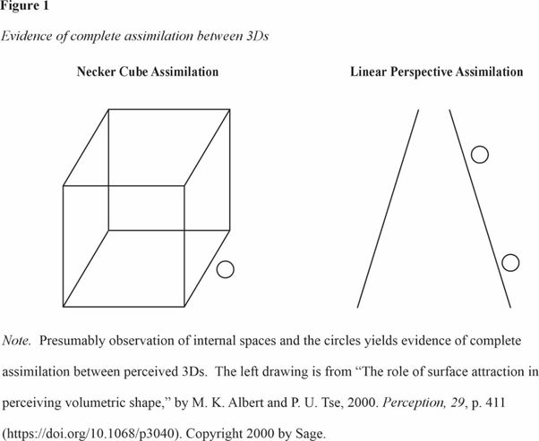
Evidence includes that presumably observation indicates that the perceived 3Ds of the objectless empty spaces of two-dimensional drawings, photographs, and videos are about the same as the perceived 3Ds of these stimuli’s close component points. For example, presumably the small white internal areas of both the Necker cube and the linear perspective drawing in Figure1 (FIGURE 1 IS AT THE END OF THIS PARAGRAPH) are perceived at about the same perceived 3D as the points of the lines to which they are closest. Also, when the Necker cube reverses, presumably the small white areas are perceived at about the same 3D as the reversed (new) perceived 3Ds of these points. Hence this observation advises that these objectless empty spaces frequently completely assimilate to the perceived 3D produced by close component points of these stimuli. This evidence occurs frequently and hence boosts the support for the assimilation between 3Ds explanation.
.
.
The same evidence advises that the assimilation between 3Ds is to a perceived 3D instead of to a physical 3D because the stimuli are two-dimensional. Much of the present section’s remaining evidence likewise advises that the assimilation between 3Ds is to a perceived 3D. Hence the assimilation between 3Ds explanation is supported.
More evidence of complete assimilation to a perceived 3D is that presumably the small circle that is external to the Necker cube of Figure 1 is perceived at about the same 3D as the perceived 3D of the closest point of the adjacent line. Similar evidence is that observing the linear perspective drawing of Figure1 and perceiving depth presumably also reveals that the perceived 3D of the physically lower (higher) circle is about the same as the relatively near (far) perceived 3D of the closest point of the adjacent line.
Monocular viewing evidence of complete assimilation to a perceived 3D follows. To begin, the Introduction indicated that the perceived 3D of a monocularly viewed rectangle became about the same as the perceived 3D of a binocularly viewed square (Gogel, 1956).
Also, the perceived 3D of a monocularly viewed small object that was centered on a window of an Ames’ distorted room and was noticeably physically farther than this window was the same as this window’s perceived 3D per Gogel and Mershon (1968).
Additionally, a monocularly viewed column-like stimulus of four somewhat different stereograms was perceived at a far fixated 3D instead of at a near perceived 3D produced by crossed disparity (Gulick & Lawson, 1976, Figure 5.8; Gulick & Lawson, 1976, Figure 5.9; Julesz, 1960, as cited in Shimojo & Nakayama, 1990; Shimojo & Nakayama, 1990).
Further, monocularly viewed small stimuli are ubiquitous because of the blind spot, and daily perception advises that these small stimuli tend to be perceived at the same 3Ds as the perceived 3Ds of the binocularly viewed areas that they are close to. Hence complete assimilation to a perceived 3D may be ubiquitous by a means other than disparity.
Additional evidence of complete assimilation to a perceived 3D is that the perceived 3D of a binocularly viewed stimulus that does not produce disparity can completely assimilate to a disparity produced perceived 3D per the present and next three paragraphs. One result was with dichoptic bars that projected to corresponding retinal points except that their two ends produced disparity (Nishina, Okada, & Kawato, 2003). A single bar was perceived. Also, the perceived 3D of this bar’s middle was about the same as the disparity produced perceived 3D at both its ends. This evidence of complete assimilation is with one perceived bar and hence an elementary perceived object. Thus it boosts the support for the assimilation between 3Ds explanation.
Complete assimilation can also be to the disparity produced perceived 3D of a different object on the basis of results of Kham and Blake (2000). One of their results occurred with a random dot stereogram that produced disparity. It resulted in the perception of a cylinder that was nearer than the surround. Also, a binocularly viewed strip that did not produce disparity was perceived as on the cylinder’s surface and hence at the same perceived 3D as the disparity produced perceived 3D.
A collection of dots can also completely assimilate per a result of Ramachandran and Cavanagh (1985). Each half of a stereogram consisted of a Kanizsa square formed by four black disks with cut outs. The vertical contours formed by the cutouts produced disparity. Binocularly viewed regularly arranged black dots that did not produce disparity were inside of each Kanizsa square. Stereoscopic viewing resulted in the perception of a Kanizsa square that was nearer in 3D than the area that surrounded it. In addition, the dots inside of this square were perceived as on its surface and hence equally near.
White areas can also completely assimilate per results of Li, Huang, Altschuler, and Tyler (2013). Each half of a stereogram resembled a wheel with spokes. The spokes of both half stereograms consisted of random dots that produced disparity. The areas (wedges) between spokes were white. They did not produce disparity. Evidence of complete assimilation is that when the random dots produced both a crossed and an uncrossed disparity, the perception was that the “white wedges between the spokes appear to have the same depth as the spokes,” p. 3.
Diplopic Percepts Have Specific Horizontal Coordinates
Much of the research literature seems to agree that diplopic percepts have specific horizontal coordinates. In accord, the present section provides a bit of evidence of this specificity.
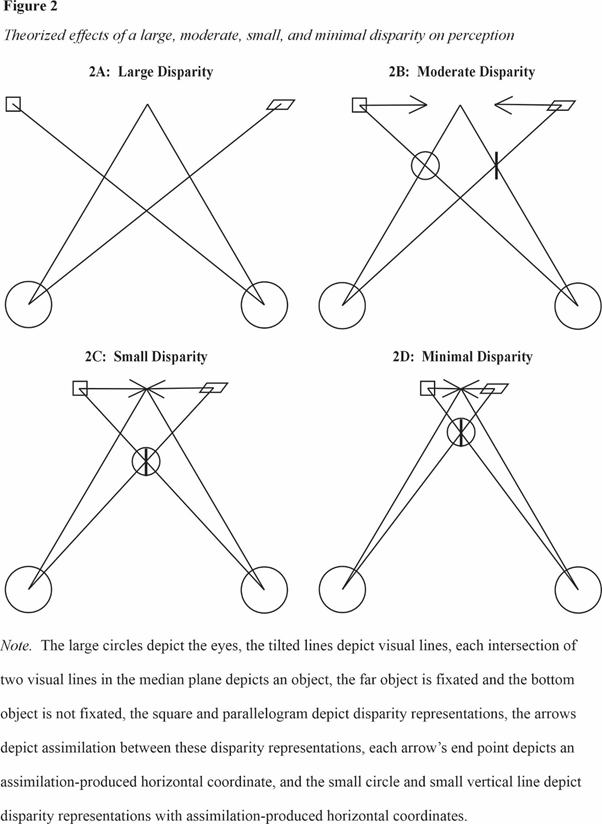
Figure 2-21 of Steinman et al. (2000) and Figure 14.4 of Howard and Rogers (2012) depict that diplopic percepts have specific horizontal coordinates. Both these figures indicate that the right eye’s disparity produced retinal image leads to a diplopic percept at a specific horizontal coordinate to the left and the disparity produced left eye’s retinal image leads to a diplopic percept at a specific horizontal coordinate to the right. Figure 2A is essentially the same as Figure 2-21 and Figure 14.4 including that it also depicts these specific left and right horizontal coordinates. It is considered in the next section.
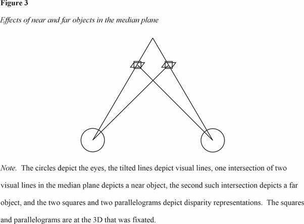
Per three sections past, near and far small objects in the median plane resulted in diplopic percepts that were at about the average of the physical 3Ds of the two objects (Cogan, 1978; Krol & van de Grind, 1980). These diplopic percepts were also to the left and right and with specific horizontal coordinates per their Figure 1s. This paper’s Figure 3 is similar and it also depicts these coordinates. It is considered in the next section.
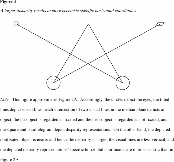
A result that Ogle (1953) noted is that a larger disparity resulted in diplopic percepts with more eccentric horizontal coordinates. Hence smaller and larger disparities resulted in horizontal coordinates that were at least sufficiently specific to be different. Figure 4 depicts diplopic percepts with more eccentric horizontal coordinates. It is considered in the next section.
A Visual Line Explanation of the Specific Horizontal Coordinates of Diplopic Percepts
The present section provides a visual line explanation of the specific left and right horizontal coordinates of diplopic percepts that the preceding section indicated. This explanation uses a premise that the Introduction’s outline of visual line explanations indicated. It is that an eye’s visual line and a disparity representation’s specific 3D usually prescribe the disparity representation’s specific horizontal coordinate. Likewise, the premise is that a visual line and a specific 3D prescribe a specific horizontal coordinate. The specific 3D is the 3D of the assimilation between 3Ds explanation. As the Introduction noted, because visual line explanations work, their premises are supported.
Figure 2A (FIGURE 2 IS AT THE END OF THIS PARAGRAPH) will be used to describe a visual line explanation of the specific horizontal coordinates that occur when disparity produced retinal images are equally to the left and right of the fovea. Figure 2A’s two left and right circles depict the two eyes. An imaginary line half way between the circles depicts the median plane. Two of Figure 2A’s visual lines intersect at a depicted relatively far physical 3D and the median plane. This intersection point is taken to depict a fixated physical object. Figure 2A also depicts that two other visual lines intersect at a depicted relatively near physical 3D and the median plane. This intersection point is taken to depict a non-fixated physical object. Because the depicted non-fixated object is not relatively close to the depicted fixated object in 3D distance, the disparity (crossed) that it produces is taken to be large.
.
.
Because Figure 2A’s visual lines intersect at the horizontal coordinates and 3Ds of its depicted physical objects, these visual lines are accurate. Accurate visual lines should be enabled by accurate neural information of the positions of the eyes’ retinal images and the eyes’ rotation.
Figure 2A depicts the two disparity representations that are enabled by the disparity produced retinal images with a square and a parallelogram. The square and parallelogram are at the 3D of the fixation object. This depiction is consistent with both the result of zero perceived depth and the assimilation between 3Ds explanation of it.
Figure 2A also shows that the square and parallelogram have specific left and right horizontal coordinates and each is on a disparity produced visual line. The explanation of these specific horizontal coordinates is that each disparity representation is on a disparity produced visual line, and this visual line and the disparity representation’s specific 3D prescribe these coordinates. This explanation uses the previously indicated premise that an eye’s visual line and a disparity representation’s specific 3D usually prescribe the disparity representation’s specific horizontal coordinate.
This understanding of Figure 2A’s depicted specific horizontal coordinates advises that the real disparities that both a non-fixated object and stereoscopically viewed dichoptic stimuli result in eventuate in disparity representations with specific horizontal coordinates in the same way. These disparity representations should then enable the diplopic percepts that are actually seen, including their specific 3D, specific horizontal coordinate, and features.
A visual line explanation of the result that near and far small objects in the median plane resulted in diplopic percepts that were to the left and right with specific horizontal coordinates is also described. This result of Cogan (1978) and Krol and van de Grind (1980) was indicated in the preceding section. Per four sections past, additional results of these papers are that fixation was at about the average of the near and far objects’ physical 3Ds and the diplopic percepts were at this average 3D. The near small object is depicted in Figure 3 (FIGURE 3 IS AT THE END OF THIS PARAGRAPH) by the nearer intersection of two visual lines in the median plane, and the far small object is depicted by the farther intersection of two additional visual lines in the median plane. These visual lines are due to disparity, because fixation was at about the average 3D. A square and a parallelogram depict each of the two disparity representations that the near and far small objects resulted in, respectively. These two squares and these two parallelograms are at about the average 3D because in the actual research the diplopic percepts were at this 3D. The squares (parallelograms) also have specific left and right horizontal coordinates, because these coordinates are presumably prescribed by the near (far) small object’s visual lines and the average 3D. Accordingly, the visual line explanation is that in the actual research, the near and far small objects resulted in four disparity representations, each of which was on a disparity produced visual line and at about the average 3D, and that each of these visual lines and this 3D prescribed the specific left or right horizontal coordinates of each disparity representation. Finishing, presumably the two disparity representations with left coordinates fused and the two disparity representations with right coordinates also fused, and these fusions account for the two diplopic percepts that were seen.
.
.
Ono’s (1984) and Howard and Rogers’ (1912) explanation of the results of Cogan (1978) and Krol and van de Grind (1980) is different. Ono maintained that one eye fixated the near object and the second eye fixated the far object. Nevertheless, Krol and van de Grind informed of the “extreme stability of the state of vergence” (p. 660) that occurred.
A visual line explanation of the preceding section’s result that a larger disparity resulted in diplopic percepts with more eccentric horizontal coordinates that are at least somewhat specific (Ogle, 1953) is also described. Figure 4 (FIGURE 4 IS AT THE END OF THIS PARAGRAPH) approximates Figure 2A including in that the far fixated object and the near non-fixated object are again depicted by the intersection of two visual lines in the median plane. The intersection point that depicts the near non-fixated object is nearer in 3D than in Figure 2A. Hence Figure 4’s non-fixated object results in a larger disparity than Figure 2A’s. Figure 4’s disparity representations, again depicted by a square and a parallelogram, are on the disparity produced visual lines and at the same 3D as in Figure 2A. Because Figure 4’s visual lines are less vertical than Figure 2A’s, the horizontal coordinates of the square and parallelogram are more eccentric than in Figure 2A, in agreement with the result. The horizontal coordinates of Figure 4’s square and parallelogram are also specific, also in agreement with the result. Accordingly, the visual line explanation maintains that the less vertical visual lines and the 3D of the disparity representations that a real larger disparity results in prescribe these disparity representations’ specific more eccentric horizontal coordinates. Completing the explanation, the two more eccentric disparity representations enable the more eccentric diplopic percepts that are actually seen.
.
.
Assimilation between Coordinates and Visual Line Explanations of Why
a Moderate Disparity Results in More Similar
Perceived Horizontal Coordinates and Perceived Depth
The present division provides evidence that a moderate disparity results in diplopic percepts with horizontal coordinates that become more similar. An assimilation between coordinates explanation of this increase in perceived similarity is then put forth. The present division then provides evidence of perceived depth between the diplopic percepts and the fixated object. An assimilation between coordinates and visual line explanation of this perceived depth is then put forth.
Diplopic Percepts with More Similar Horizontal Coordinates
The present section provides evidence that a moderate disparity results in diplopic percepts with horizontal coordinates that become more similar. This result is not considered by analyses of the effects of disparity (Blake & Wilson, 2011; Ding & Levi, 2021; Howard & Rogers, 2012; Patterson & Martin, 1992; Vishwanath, 2014; Wilcox & Allison, 2009). This result is considered by additional analyses (Anderson & Nakayama, 1994; von Tschermak-Seysenegg, 1952; Werner, 1937). These analyses will be covered three sections henceforth.
Werner (1937) provided evidence that horizontal coordinates become more similar. A nearer vertical thread was fixated. A farther non-fixated vertical thread was also present and it resulted in diplopic percepts. The result was that the horizontal coordinate of one diplopic percept was perceived as more similar to the horizontal coordinate of the second diplopic percept than when the view of the second diplopic percept was blocked.
Evidence also occurred when dichoptic vertical bars produced disparity (Rose & Blake, 1988). A disparity of 1.0 deg and similar disparities resulted in diplopic percepts with horizontal coordinates that were perceived as more similar to each other than when the same eye viewed both bars.
Stereoscopic viewing also resulted in the “mutual approach of the double images” (von Tschermak-Seysenegg, 1952, p. 181).
The disparity that occurs with free fusion can also result in more similar horizontal coordinates. When a stimulus consists of a left and right object and each object results in diplopic percepts, “two of the four perceived views will move progressively closer to one another” (Steinman et al., 2000, p. 325). That is, the horizontal coordinates of the two middle diplopic percepts become more similar.
Evidence that a moderate but not a large disparity results in this increase in similarity is that a sufficiently large disparity resulted in a “near zero” increase in this similarity (Ross & Blake, 1988).
An Assimilation between Coordinates Explanation of Why the Horizontal Coordinates of
Diplopic Percepts Become More Similar
The present section puts forth an assimilation between coordinates explanation of the preceding section’s result that a moderate disparity results in diplopic percepts with horizontal coordinates that become more similar. The explanation basically is that this increase in perceived similarity is due to the horizontal coordinate of a disparity representation to the left assimilating (becoming similar) to the horizontal coordinate of a disparity representation to the right and vice versa.
Figure 2B (FIGURE 2B IS PART OF FIGURE 2) depicts effects of a moderate disparity. It helps to describe and support the assimilation between coordinates explanation of these effects.
The visual lines of Figure 2B that intersect at the farther 3D and in the median plane are the same as in Figure 2A. Accordingly, their intersection point again depicts the fixated object and its 3D and horizontal coordinate.
The visual lines of Figure 2B that intersect at the nearer 3D and in the median plane differ from those in Figure 2A. Nevertheless, their intersection point again depicts the disparity producing non-fixated object and its 3D and horizontal coordinate. This intersection point is closer in 3D distance to the depicted fixated object than in Figure 2A, consistent with Figure 2B’s depiction of a moderate disparity.
Per the preceding division’s assimilation between 3Ds and visual line explanations, the two disparity representations that the non-fixated object results in are at the perceived 3D that occurs with fixation and with specific left and right horizontal coordinates. Figure 2B depicts these disparity representations with a square and a parallelogram, as in Figure 2A.
Importantly, the assimilation between coordinates explanation claims that the horizontal coordinates of the left and right disparity representations assimilate and by this means explains why these coordinates become more similar. This assimilation is depicted by Figure 2B’s two arrows. The arrows start at the square and parallelogram that depict the left and right disparity representations and aim toward the other shape. Each arrow’s end point depicts the assimilation-produced horizontal coordinate.
The assimilation between coordinates explanation also claims that the assimilation between the horizontal coordinates of the left and right disparity representations is partial. A partial assimilation between two coordinates occurs when the increase in their similarity is not so large that the two coordinates become the same. Accordingly, the end points of the two arrows in Figure 2B are different instead of the same. This partial assimilation accounts for why the horizontal coordinates of the diplopic percepts become more similar but are still different.
The assimilation between coordinates explanation also claims that the amounts by which the horizontal coordinates of the two disparity representations assimilate toward each other can be equal. Likewise, it maintains that this assimilation can be unweighted. Accordingly, the length of each arrow in Figure 2B depicts the amount by which one disparity representation’s horizontal coordinate assimilates toward the second disparity representation’s horizontal coordinate and these lengths are equal.
Figure 2B depicts the disparity representations with assimilation-produced horizontal coordinates with a circle and a short vertical line. Hence the horizontal coordinates of this circle and short vertical line are the same as the assimilation-produced horizontal coordinates that the end of each arrow indicates. The circle and short vertical line are also nearer in 3D, as is considered two sections henceforth.
Presumably two real (not depicted) disparity representations with assimilation-produced horizontal coordinates also occur and enable the two disparity percepts that are actually seen. Also, due to this assimilation, the diplopic percepts’ horizontal coordinates are perceived as more similar, which is as to be explained.
The assimilation between coordinates explanation also explains why a moderate disparity but not a large disparity results in assimilation between the horizontal coordinates of disparity representations. A first point is that prior to the assimilation between the disparity representations’ left and right horizontal coordinates, a moderate disparity results in disparity representations with left and right horizontal coordinates that are closer to each other than for a large disparity. This point is supported with the help of Figures 2B and 2A. They depict that Figure 2B’s retinal images are less peripheral than Figure 2A’s. Hence they also depict that Figure 2B’s disparity produced visual lines are more vertical than Figure 2A’s. Thus they also depict that the left and right horizontal coordinates of Figure 2B’s square and parallelogram are closer to each other than are the horizontal coordinates of Figure 2A’s square and parallelogram. So the first point is supported. A second point is that closer physical horizontal coordinates result in more assimilation between these coordinates than less close physical horizontal coordinates (Born et al., 2016; Ganz, 1964; Rentschler et al., 1975). Therefore a moderate disparity should result in more assimilation between the horizontal coordinates of disparity representations than a large disparity, which is essentially as to be explained.
It is also noted that when two physical horizontal coordinates are quite close to each other, a smaller instead of a larger absolute amount of assimilation between them occurs. An illustration of why is that when two horizontal coordinates differ by 1 mm, then the absolute amount of assimilation between them can be no more than this 1 mm.
A Moderate Disparity Also Results in Perceived Depth
The present section provides evidence that a moderate disparity also results in perceived depth. That is, the diplopic percepts’ perceived 3D is nearer or farther than the fixated object’s perceived 3D. This evidence follows.
Disparity resulted in both diplopic percepts and perceived depth (Hibbard, Haines, & Hornsey, 2017; Ogle, 1953; Richards, 1971). Richards, for example, measured the perceived 3D of the diplopic percepts by viewers reproducing the 3D that they perceived. Ogle noted the occurrence of diplopic percepts, Richards indicated the occurrence of diplopic percepts, and Hibbard et al. asked viewers to decide whether or not diplopic percepts were seen. Richards also showed that a larger disparity resulted in minimal perceived depth.
Evidence also comes from a discrimination result. A smaller disparity resulted in a better discrimination between the 3D of diplopic percepts and the 3D of the fixation object than a larger disparity (Westheimer & Tanzman, 1956). This result is evidence, because the better discrimination presumably predicts a lower similarity between the perceived 3D of the diplopic percepts and the perceived 3D of the fixation object, likewise, more perceived depth.
An Assimilation between Coordinates and Visual Line Explanation of Why a Moderate
Disparity Results in Perceived Depth
The present section indicates and supports an assimilation between coordinates and visual line explanation of why a moderate disparity results in perceived depth between diplopic percepts and the fixated object. Analyses of effects of disparity that did not consider assimilation were indicated three sections past. There are also analyses of effects of disparity that did not consider a visual line explanation (the same past analyses; Anderson & Nakayama, 1994; von Tschermak-Seysenegg, 1952; Werner, 1937).
An explanation of perceived depth that was based on assimilation was indicated by Werner (1937). Werner observed that as the horizontal coordinates of diplopic percepts became more similar, more depth was perceived. He also gave precedence to assimilation: “if there is such a displacement … there will follow a movement of … depth,” p. 23. (“Displacement” is Werner’s term for the assimilation.) Werner’s observation is also evidence that the assimilation between horizontal coordinates and perceived depth that a moderate disparity results in can be perceived to be co-occurring.
Almost the same explanation was indicated by von Tschermak-Seysenegg (1952). He also observed that as the horizontal coordinates of diplopic percepts became more similar, more depth was perceived. He wrote that “the stronger horizontal shrinking, the greater is the positive or negative increase in distance,” p. 180, hence also giving precedence to assimilation. (“Horizontal shrinking” refers to assimilation between the horizontal coordinates of diplopic percepts.) He also referred to the “Assimilation of Visual Directions,” p. 180. von Tschermak-Seysenegg’s observation is more evidence that the assimilation between horizontal coordinates and perceived depth that a moderate disparity results in can be perceived to be co-occurring.
Anderson and Nakayama (1994) indicated that allelotropia, which is like assimilation between horizontal coordinates, is associated with perceived depth. But they did not give precedence to allelotropia.
The present explanation of perceived depth follows. Recollecting, Figure 2B depicts disparity representations with assimilation-produced horizontal coordinates with a circle and a short vertical line. It also shows that the horizontal coordinates of this circle and short vertical line are the same as the assimilation-produced horizontal coordinates that the end of each arrow indicates. Significantly, both the circle and small vertical line are on one or the other of the disparity produced visual lines. This positioning agrees with the understanding that a disparity representation is on its visual line. The circle’s and short vertical line’s assimilation-produced horizontal coordinates and the disparity produced visual lines then prescribe the circle’s and short vertical line’s 3Ds per the premise of the visual line explanation that a visual line and a specific horizontal coordinate prescribe a specific 3D. Figure 2B shows that these prescribed 3Ds are nearer than the fixation 3D.
Accordingly, the assimilation between coordinates and visual line explanation maintains that assimilation between the horizontal coordinates of two real (not depicted) disparity representations results in each disparity representation’s assimilation-produced horizontal coordinate and its visual line enabling its nearer 3D. The two real disparity representations then enable actually seen nearer diplopic percepts and hence the perceived depth that is to be explained.
Examination of Figure 2B also reveals that more assimilation between the horizontal coordinates of the depicted disparity representations is predicted to result in nearer depicted disparity representations and hence nearer diplopic percepts. Hence, for crossed disparities, both evidence of more assimilation and factors that should result in more assimilation are predicted to be associated with nearer diplopic percepts.
Assimilation between Coordinates and Visual Line Explanations
of Why a Small Disparity Results in a Perceived Midline Coordinate
and Accurate Perceived Depth
The present division provides evidence that, for disparity produced retinal images that are equally to the left and right of the fovea, a small disparity results in a perceived midline coordinate. A disparity produced single object (hence features) is also perceived at the midline coordinate. The present division then provides an assimilation between coordinates explanation of the perceived midline coordinate that is like the preceding division’s explanation of perceived horizontal coordinates that become more similar. It also provides evidence that the perceived depth between the disparity produced perceived single object and the fixation object is accurate, that is, the same as geometrically predicted. It then provides an assimilation between horizontal coordinates and visual line explanation of this accurate perceived depth that is like the preceding division’s explanation of the perceived depth of diplopic percepts. It then shows that the result that a small disparity and a moderate disparity can result in about the same perceived 3D is largely accounted for by an assimilation between coordinates explanation.
A Small Disparity Results in a Perceived Midline Coordinate
The present section provides evidence that, for disparity produced retinal images that are equally to the left and right of the fovea, a small disparity results in a perceived midline coordinate. It also provides evidence that a single object (hence features) is perceived at the midline coordinate.
Evidence that a small disparity results in a perceived midline coordinate is that daily viewing indicates that the perceived coordinate of a non-fixated object in the median plane is usually the midline coordinate, as evidenced by the perception of the non-fixated object’s features at this coordinate. More restricted viewing of an object in the median plane that produces a small disparity also results in a perceived midline coordinate, for example, when the horopter is determined.
The disparity that occurs with free fusion also results in a perceived midline coordinate. When free fusion of a left and a right object with matching features comes about, four diplopic percepts are also perceived, and at another instance the perception of the two middle diplopic percepts and their left and right horizontal coordinates is replaced by the perception of an in between horizontal coordinate as evidenced by the perception of the diplopic percepts’ features at this coordinate (Steinman et al., 2000, p. 325).
Evidence of a perceived midline coordinate also stems from stereograms (Kaufman, 1974, p. 282; Ono, Angus, & Gregory, 1977; Sheedy, 1930, as cited in Sheedy & Fry, 1979). These stereograms are similar. Ono et al.’s results are considered. In one half stereogram, a small disk was to the left of the center of a rectangle and in the second half stereogram a small disk was to the right of the center of a rectangle. The two rectangles produced zero disparity. Hence the two disks produced disparity. These disks resulted in a perceived midline coordinate, as evidenced by the perception of the disks’ features at this coordinate.
Another result of Ono et al. (1977) was that a larger disparity resulted in diplopic percepts. This result is evidence that a small but not a moderate disparity results in a perceived midline coordinate.
Evidence of a perceived midline coordinate also comes from monocular viewing of a left object and a right object. Viewing a left object with the left eye, viewing a right object with matching features with the right eye, and fixating on a farther stimulus in the median plane resulted in a perceived midline coordinate as evidenced by the perception of the near objects’ features at this coordinate (Wells, 1792, as cited in Ono et al., 2003). Also, viewing a left house with the right eye, a right tree with the left eye, and fixating on a nearer point in the median plane resulted in the perception of a midline coordinate as evidenced by the features of both the house and the tree at this coordinate (Hering, 1879, as cited in Ono et al., 2003).
An Assimilation between Coordinates Explanation of Why a Small Disparity Results
in a Perceived Midline Coordinate
The present section indicates an assimilation between coordinates explanation of why a small disparity results in a perceived midline coordinate. This explanation is outlined as follows. As for a moderate disparity, this explanation maintains that the disparity representations’ left and right coordinates assimilate (become more similar). Critically, the amount by which each horizontal coordinate assimilates to the other horizontal coordinate is so large that the two horizontal coordinates that eventuate are the same. In addition, when the amounts of these two assimilations are equal, each assimilation-produced horizontal coordinate is the unweighted average of the disparity representations’ left and right horizontal coordinates. Due to the unweighted averaging, each horizontal coordinate is also the midline coordinate. So, two assimilation-produced midline coordinates eventuate. These two coordinates then fuse to result in the single perceived midline coordinate that is to be explained.
Figure 2C (FIGURE 2C IS PART OF FIGURE 2) helps to additionally describe and support this assimilation between coordinates explanation. Figure 2C’s points of intersection of two visual lines in the median plane again depict the fixated and non-fixated objects. Figure 2C depicts that the fixated object is at the same 3D as in Figure 2B, which, recall, depicts effects of a moderate disparity. Figure 2C also depicts that the non-fixated object that produces disparity is closer in 3D distance to the fixated object than in Figure 2B. Hence Figure 2C depicts what has been called a small disparity.
A small disparity normally results in retinal images that are less peripheral than for a moderate disparity. In accord, the disparity produced retinal images are less peripheral in Figure 2C than in Figure 2B. The consequence is that the disparity produced visual lines are more vertical in Figure 2C than in Fig 2B.
As in Figure 2B, Figure 2C’s depicted disparity representations, that is, the square and parallelogram, are at the same 3D as the fixated object’s 3D. Also as in Figure 2B (also Figure 2A), both this square and parallelogram are on a disparity produced visual line and at a specific left or right horizontal coordinate.
Because Figure 2C’s disparity produced visual lines are more vertical than Figure 2B’s, the horizontal coordinates of Figure 2C’s square and parallelogram are closer to each other than are Figure 2B’s. Accordingly, the assimilation between coordinates explanation claims that a small disparity ordinarily results in disparity representations with horizontal coordinates that are closer to each other than for a moderate disparity.
Critically, the assimilation between coordinates explanation proposes that a small disparity results in left and right disparity representations that are sufficiently close to each other that their assimilation-produced horizontal coordinates become so similar to each other that each coordinate is the same as the other coordinate. This sufficient closeness proposal is supported: Two closer objects result in a larger amount of assimilation between their coordinates than two less close objects (Born et al., 2016; Ganz, 1964; Rentschler et al., 1975).
Figure 2C depicts this proposed assimilation, including the two assimilation-produced horizontal coordinates that have become the same as each other. Like Figure 2B, Figure 2C depicts the assimilation between the horizontal coordinates of the depicted left and right disparity representations (the square and parallelogram) with two arrows. Also, each of these arrows starts at a depicted disparity representation and points toward the other one. Additionally, the end of each arrow depicts the assimilation-produced horizontal coordinate of each disparity representation. These two ends are at the same horizontal coordinate.
This assimilation between the left and right horizontal coordinates of the disparity representations is probably frequently unweighted. Accordingly, Figure 2C shows that the ends of both arrows meet at the unweighted average of the left and right coordinates of the square and parallelogram. This unweighted average coordinate is also the midline coordinate. The two assimilation-produced both average and midline coordinates then fuse to result in the single perceived midline coordinate that is to be explained.
A Small Disparity Results in Accurate Perceived Depth
The present section provides evidence that a small disparity results in accurate perceived depth, that is, perceived depth that is accurately predicted. This depth is between the perceived 3D that a small disparity results in and the perceived 3D that occurs with fixation. A past understanding is also supported.
Evidence of this accurate perceived depth comes from Hartle and Wilcox (2016), Ogle (1953), and Richards (1971). The Richards result is considered. Dichoptic vertical lines produced disparity. The disparity-produced 3D was measured by reproduction of the apparently perceived 3D. Whether a single line was perceived or whether diplopic percepts were seen was also indicated. Perceived depth closely approximated geometrically predicted perceived depth up to about .5 deg disparity. A single line was perceived up to approximately the same disparity, consistent with previously indicated evidence that a small disparity results in a single perceived object.
The previously mentioned past understanding is that the perceived 3D that occurs with fixation is ordinarily accurate. If this perceived 3D were not accurate, accurate perceived depth would hardly occur. Hence the understanding is supported by the evidence of accurate perceived depth.
An Assimilation between Coordinates and Visual Line Explanation of Why a Small
Disparity Results in Accurate Perceived Depth
The present section describes and supports an assimilation between coordinates and visual line explanation of why a small disparity results in accurate perceived depth. An explanation of accurate perceived depth was not considered (Anderson & Nakayama, 1994; Blake & Wilson, 2011; Ding & Levi, 2021; Howard & Rogers, 2012; Patterson & Martin, 1992; Vishwanath, 2014; Wilcox & Allison, 2009), and accurate perceived depth was not predicted (von Tschermak-Seysenegg, 1952; Werner, 1937).
A claim of the present section’s explanation is that the 3D of disparity representations with assimilation-produced average horizontal coordinates is frequently the same as the 3D of the intersection point of the disparity produced visual lines. This claim is supported with the help of Figure 2C. As was indicated, the ends of Figure 2C’s two arrows depict that the assimilation-produced horizontal coordinates of both disparity representations are the average of these disparity representations’ left and right horizontal coordinates. As in Figure 2B, the two disparity representations with assimilation-produced horizontal coordinates are depicted by a circle and a short vertical line. Figure 2C depicts the sameness of the two disparity representations’ assimilation-produced average horizontal coordinates by the short vertical line being a diameter of the circle. Hence Figure 2C shows that both the circle and short vertical line are at the assimilation-produced average horizontal coordinate. Significantly, Figure 2C also shows that both the circle and short vertical line are located at the intersection point of the disparity produced visual lines. The reason is that this location means that the disparity representations that the circle and short vertical line depict are on their disparity produced visual lines. Also, this location shows that the 3D of the disparity representations that this circle and line depict is the same as the 3D of the intersection point of the disparity produced visual lines. In accord, the 3D of these depicted disparity representations is prescribed by their horizontal coordinate and their disparity produced visual lines per the visual line explanation (as for a moderate disparity). This 3D then advises that for a real small disparity, the 3D of two disparity representations with assimilation-produced average horizontal coordinates is also frequently the same as the 3D of the intersection point of the disparity produced visual lines, which is as claimed.
The 3D of the intersection point of Figure 2C’s disparity producing visual lines is accurate because this 3D is also the physical 3D of the non-fixated object. The preceding paragraph concluded that the 3Ds of the two disparity representations with assimilation-produced average horizontal coordinates is frequently the same as the 3D of this intersection point and hence this accurate 3D. Hence the 3Ds of these two disparity representations should also tend to be accurate.
Presumably the 3Ds of the two real (not depicted) disparity representations with assimilation-produced average horizontal coordinates fuse to result in the single 3D that is perceived. The preceding paragraph advises that the 3Ds of these two real disparity representations tend to be accurate. Hence this single perceived 3D should also tend to be accurate. Thus the perceived depth should also tend to be accurate, as to be explained.
An Assimilation between Coordinates Explanation of Why a Small and a Moderate
Disparity Can Result in About the Same Perceived 3D
The perceived 3D of the single object that a small disparity results in and the perceived 3D of the diplopic percepts that a moderate disparity results in can be about the same (Ogle, 1953; Richards, 1971). The present section indicates an assimilation between coordinates explanation of this sameness.
A claim of this explanation is that both a small and a moderate disparity can result in about the same amount of assimilation between the left and right horizontal coordinates of the disparity representations. This claim is supported as follows. Per the present division, a small disparity results in two disparity representations that have the same assimilation-produced average horizontal coordinates. This assimilation is called complete, in that two coordinates that are the same cannot become more similar. Per the preceding division, a moderate disparity results in two disparity representations with assimilation-produced horizontal coordinates that become more similar but do not become the same. This assimilation was called partial assimilation. A small disparity also results in disparity representations with left and right horizontal coordinates that are closer to each other than for a moderate disparity per three sections past. This difference in closeness is depicted by the horizontal coordinates of the square and parallelogram in Figures 2C and 2B. A complete assimilation between two horizontal coordinates works toward producing a larger amount of assimilation between them. In contrast, two closer horizontal coordinates work toward producing a smaller amount of assimilation between them. This is because, for example, if two horizontal coordinates are as close as 1 mm, then the maximal amount of assimilation between them can only be this 1 mm. Hence there are two opposing influences on the amount of assimilation between the left and right horizontal coordinates of the disparity representations that a small and a moderate disparity result in. Thus it can be expected that a small disparity and a moderate disparity can result in about the same amount of this assimilation. Therefore the claim is supported. Accordingly, the equal lengths of the arrows of Figures 2C and 2B depict that a small and a moderate disparity result in the same amount of this assimilation.
Significantly, the depicted 3Ds of the circle and short vertical line of both Figures 2C and 2B are approximately the same. Examination of Figures 2C and 2B reveals that this approximate sameness occurs because of the depicted equal amounts of assimilation between left and right horizontal coordinates and because the tilts of the disparity produced visual lines are not too dissimilar.
The explanation for real small and moderate disparities is analogous: A small and a moderate disparity may result in about the same amount of assimilation between the left and right horizontal coordinates of the disparity representations, they may also result in disparity produced visual lines with tilts that are not too dissimilar, and hence they also result in two assimilation-produced disparity representations with 3Ds that are about the same. Finishing, the two 3Ds that the small disparity results in fuse to yield a single perceived 3D, and it is about the same as the perceived 3D of the diplopic percepts that a moderate disparity results in, as to be explained.
An Assimilation between Coordinates and Visual Line Explanation
of Why a Minimal Disparity Results in
Less Perceived Depth than a Small Disparity
A minimal disparity results in less perceived depth than a small disparity (e.g. Hartle & Wilcox, 2016; Ogle, 1953; Richards, 1971). The present division indicates an assimilation between coordinates and visual line explanation of this less perceived depth.
Effects of a minimal disparity and small disparity otherwise correspond. Accordingly, the following explanation of this less perceived depth closely resembles the preceding division’s explanation of the perceived depth that a small disparity results in.
Figure 2D (FIGURE 2D IS PART OF FIGURE 2) helps to explain this less perceived depth. The intersection points of the visual lines in the median plane again depict the far fixated and near non-fixated objects. The 3D of the intersection point of the disparity produced visual lines is closer to the 3D of the farther intersection point in Figure 2D than in Figure 2C. Hence Fig 2D depicts both a minimal disparity and less physical depth. The ends of Figure 2D’s two arrows depict that the assimilation between the left and right coordinates of the disparity representations that are depicted by a square and parallelogram results in two horizontal coordinates, each of which is an average of these left and right coordinates and also the midline coordinate, as in Figure 2C. In support of this depiction, an average horizontal coordinate was perceived and the disparity was as small as 15’ (Ono et al., 1977). Figure 2D depicts the two disparity representations with assimilation-produced average horizontal coordinates with a circle and a short vertical line that is a diameter of this circle, as in Figure 2C. Figure 2D shows that the circle’s and short vertical line’s horizontal coordinate and the horizontal coordinate of the intersection of the disparity produced visual lines are the same. Significantly, Fig 2D also shows that the circle and short vertical line are at the intersection of the disparity produced visual lines, as in Figure 2C. The reason for this location is that each disparity representation is then on its disparity produced visual line, as for a small disparity. The horizontal coordinate of this location and the disparity produced visual lines then prescribe that the 3D of the disparity representations is the same as the 3D of this location, which is what Figure 2D depicts. Recollecting, this 3D is closer to the 3D of the farther intersection point than in Figure 2C. Therefore this closer 3D signifies the less perceived depth that is to be explained.
Discussion
Effects of a large to a minimal disparity on perceived depth and perceived horizontal coordinates have been reasoned to be enabled by assimilation between three-dimensional distances (3Ds), assimilation between horizontal coordinates, and disparity produced visual lines. It has also been indicated that previous analyses do not explain the accurate depth result and they at best partially explain the horizontal coordinate results.
Evidence that complete assimilation between 3Ds frequently occurs was also gathered. This evidence included that this assimilation occurs ubiquitously during daily viewing.
When considering the effects of a small disparity, it was reasoned that assimilation between two horizontal coordinates enables the perception of a single coordinate that is an average of left and right horizontal coordinates. Hence a suggestion is that an assimilation-produced averaging of the horizontal coordinates of two objects enables both the perception of an about average of their coordinates (Hazeltine et al., 1997) and a saccade that aims at about the average of their coordinates (Coren & Hoenig, 1972; Van der Stigchel & Nijboer, 2013). A similar suggestion is that an assimilation-produced averaging among the coordinates of the points comprising a perimeter of a shape enables the perception of an approximate average of these coordinates (Vishwanath & Kowler, 2003) and fixation that aims at an approximate average of these coordinates (Kaufman & Richards, 1969).
Presumably it is accepted that non-spatial features are perceived at the perceived 3D and horizontal coordinate that a disparity results in. Because this 3D and horizontal coordinate have been reasoned to be enabled by assimilation between 3Ds and assimilation between horizontal coordinates, these non-spatial features are not perceived at the 3D and horizontal coordinate that would be perceived if these assimilations did not occur. For example, non-spatial features are frequently not perceived at the specific left and right coordinates of two disparity representations. Instead, the non-spatial features “tag along with” the assimilation-produced change in these horizontal coordinates.
An explanation of this assimilation-produced tagging along is that the neural representations for a specific 3D and specific horizontal coordinate enable non-spatial features to be at this 3D and coordinate. Likewise, this explanation maintains that non-spatial features are bound to a 3D and horizontal coordinate because the neural representations for this 3D and horizontal coordinate enable this binding. This explanation also accounts for the outcome that non-spatial features also tag along with experimentally demonstrated assimilation-produced 3Ds (e.g. Gogel, 1956) and assimilation-produced horizontal coordinates (e.g. Ganz, 1964) instead of remaining where they would be if these assimilations did not occur.
Nevertheless analyses that bear on the binding of non-spatial features to a 3D and coordinate do not consider the occurrence of assimilation between 3Ds and horizontal coordinates (Kovacs & Harris, 2019; Luck, Hillyard, Mouloua, & Hawkins, 1996; Treisman & Gelade, 1980; van Dam & Hommel, 2010; van der Heijden, 1993). This lack of interest amounts to one more indication that the influence of assimilation on visual spatial perception has been underestimated.
References
Anderson, B. L., & Nakayama, K. (1994). Toward a general theory of stereopsis: Binocular matching, occluding contours, and fusion. Psychological Review, 101(3), 414–445. https://doi.org/10.1037/0033-295X.101.3.414
Blake, R., & Wilson, H. (2011). Binocular vision. Vision Research, 51(7), 754–770. https://doi.org/10.1016/j.visres.2010.10.009
Blakemore, C. (1970). The range and scope of binocular depth discrimination in man. Journal of Physiology, 2ll, 599-622.
Born, S., Kruger, H. M., Zimmermann, E., & Cavanagh, P. (2016). Compression of space for low visibility probes. Frontiers in Systems Neuroscience, 10, Article 21. https://doi:10.3389/fnsys.2016.00021
Cogan, A. I. (1978). Qualitative observations in visual science: “The Farnsworth Shelf:” Fusion at the site of the “ghosts.” Vision Research,18(6), 657–664.https://doi.org/10.1016/0042-6989(78)90145-1
Ding, J., & Levi, D. M. (2021). A unified model for binocular fusion and depth perception. Vision Research, 180, 11–36. https://doi.org/10.1016/j.visres.2020.11.009
Foley, J. M., Applebaum, T. H., & Richards, W. A. (1975). Stereopsis with large disparities: Discrimination and depth magnitude. Vision Research, 15(3), 417-421. https://doi.org/10.1016/0042-6989(75)90091-7
Ganz, L. (1964). Lateral inhibition and the location of visual contours: An analysis of figural after-effects. Vision Research, 4(9-10), 465-481. https://doi:10.1016/0042-6989(84)90137-8
Gogel, W. C. (1956). The tendency to see objects as equidistant and its inverse relation to lateral separation. Psychological Monographs: General and Applied, 70(4), 1–17. https://doi.org/10.1037/h0093713
Gogel, W. C., & Mershon, D. H. (1968). The perception of size in a distorted room. Perception & Psychophysics,4(1), 26–28. https://doi.org/10.3758/BF03210442
Gulick, W. L., & Lawson, R. B. (1976). Human stereopsis: A psychophysical approach. Oxford University Press.
Hartle, B., & Wilcox, L. M. (2016). Depth magnitude from stereopsis: Assessment techniques and the role of experience. Vision Research, 125, 64–75. https://doi.org/10.1016/j.visres.2016.05.006
Hazeltine, R. E., Prinzmetal, W., & Elliott, K. (1997). If it’s not there, where is it? Locating illusory conjunctions. Journal of Experimental Psychology: Human Perception and Performance, 23(1), 263-277. https://doi.org/10.1037/0096-1523.23.1.263
Hibbard, P. B., Haines, A. E., & Hornsey, R. L. (2017). Magnitude, precision, and realism of depth perception in stereoscopic vision. Cognitive Research: Principles and Implications, 2(25), 1-11. https://doi.org/10.1186/s41235-017-0062-7
Howard, I. P., & Rogers, B. J. (2012). Perceiving in depth. (Vol. 2 Stereoscopic vision). Oxford University Press.
Kaufman, L. (1974). Sight and mind: An introduction to visual perception. Oxford University Press.
Kham, K., & Blake, R. (2000). Depth capture by kinetic depth and by stereopsis. Perception, 29(2), 211-220. https://doi:10.1068/p3011
Kovacs, O., & Harris, I. M. (2019). The role of location in visual feature binding. Attention, Perception, & Psychophysics, 81(5), 1551–1563. https://doi.org/10.3758/s13414-018-01638-8
Krol, J. D., & Van de Grind, W. A. (1980). The double-nail illusion: Experiments on binocular vision with nails, needles, and pins. Perception, 9(6), 651–669. https://doi.org/10.1068/p090651
Li, X., Huang, A. E., Altschuler, E. L., & Tyler, C. W. (2013). Depth spreading through empty space induced by sparse disparity cues. Journal of Vision, 13(10), Article 7. https://doi.org/10.1167/13.10.7
Luck, S. J., Hillyard, S. A., Mouloua, M., & Hawkins, H. L. (1996). Mechanisms of visual–spatial attention: Resource allocation or uncertainty reduction? Journal of Experimental Psychology: Human Perception and Performance, 22(3), 725–737. https://doi.org/10.1037/0096-1523.22.3.725
Ogle, K. N. (1953). Precision and validity of stereoscopic depth perception from double images. Journal of the Optical Society of America, 43, 906–913. https://doi.org/10.1364/JOSA.43.000906
Ono, H. (1984). Exorcising the double-nail illusion: Giving up the ghost. Perception, 13, 753-758. https://doi.org/10.1068/p130753
Ono, H., Angus, R., & Gregory, P. (1977). Binocular single vision achieved by fusion and suppression. Perception & Psychophysics, 21(6), 513–521. https://doi.org/10.3758/BF03198731
Ono, H., Lillakas, L., Grove, P. M., & Suzuki, M. (2003). Leonardo’s constraint: Two opaque objects cannot be seen in the same direction. Journal of Experimental Psychology: General, 132(2), 253–265. https://doi.org/10.1037/0096-3445.132.2.253
Nishina, S., Okada, M., & Kawato, M. (2003). Spatio-temporal dynamics of depth propagation on uniform region. Vision Research, 43(24), 2493–2503. https://doi.org/10.1016/S0042-6989(03)00439-5
Patterson, R., & Martin, W. L. (1992). Human stereopsis. Human Factors, 34(6), 669–692.
Prinzmetal, W. (2005). Location perception: The X-Files parable. Perception & Psychophysics, 67(1), 48-71. https://doi:10.3758/BF03195012
Ramachandran, V. S., & Cavanagh, P. (1985). Subjective contours capture stereopsis. Nature, 317(6037), 527–530. https://doi.org/10.1038/317527a0
Rentschler, I., Hilz, R., & Grimm, W. (1975). Processing of positional information in the human visual system. Nature, 253(5491), 444-445. https://doi:10.1038/253444a0
Richards, W. Anomalous stereoscopic depth perception. (1971). Journal of the Optical Society of America, 61(3), 410-414.
Richards, W., & Kaye, M. G. (1974). Local versus global stereopsis: Two mechanisms? Vision Research, 14(12), 1345–1347. https://doi.org/10.1016/0042-6989(74)90008-X
Rose, D., & Blake, R. (1988). Mislocalization of diplopic images. Journal of the Optical Society of America, A, Optics, Image & Science, 5(9), 1512-1521. https://doi.org/10.1364/JOSAA.5.001512
Sheedy, J. E., & Fry, G. A. (1979). The perceived direction of the binocular image. Vision Research, 19(2), 201211. https://doi.org/10.1016/0042-6989(79)90051-8
Shimojo, S., & Nakayama, K. (1990). Real world occlusion constraints and binocular rivalry. Vision Research 39(1), 6980. https://doi.org/10.1016/0042-6989(90)90161-D
Smith, K. (1954). ‘Attraction’ in figural after-effects. American Journal of Psychology, 67, 174-176. https://doi.org/10.2307/1418089
Steinman, S. B., Steinman, B. A., & Garzia, R. P. (2000). Foundations of binocular vision: A clinical perspective. McGraw-Hill.
Treisman, A. M., & Gelade, G. (1980). A feature-integration theory of attention. Cognitive Psychology, 12(1), 97–136. https://doi.org/10.1016/0010-0285(80)90005-5
van der Heijden, A. H. C. (1993). The role of position in object selection in vision. Psychological Research, 56(1), 44–58. https://doi.org/10.1007/BF00572132
van Dam, W. O., & Hommel, B. (2010). How object-specific are object files? Evidence for integration by location. Journal of Experimental Psychology: Human Perception and Performance, 36(5), 1184–1192. https://doi.org/10.1037/a0019955
Vishwanath, D. (2014). Toward a new theory of stereopsis. Psychological Review, 121(2), 151–178. https://doi.org/10.1037/a0035233
von Tschermak-Seysenegg, A. (1952). Introduction to physiological optics. Thomas.
Werner, H. (1937). Dynamics in binocular depth perception. Psychological Monographs, 49(2), i-127. https://doi.org/10.1037/h0093526
Westheimer, G., & Tanzman, I. J. (1956). Qualitative depth localization with diplopic images. Journal of the Optical Society of America, 46, 116–117. https://doi.org/10.1364/JOSA.46.000116
Wilcox, L. M., & Allison, R. S. (2009). Coarse-fine dichotomies in human stereopsis. Vision Research, 49(22), 2653–2665. https://doi.org/10.1016/j.visres.2009.06.004